.webp)
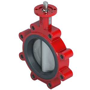
Engineered to Resist Aggressive Chemicals with Reliable Performance and A Variety of Material Options
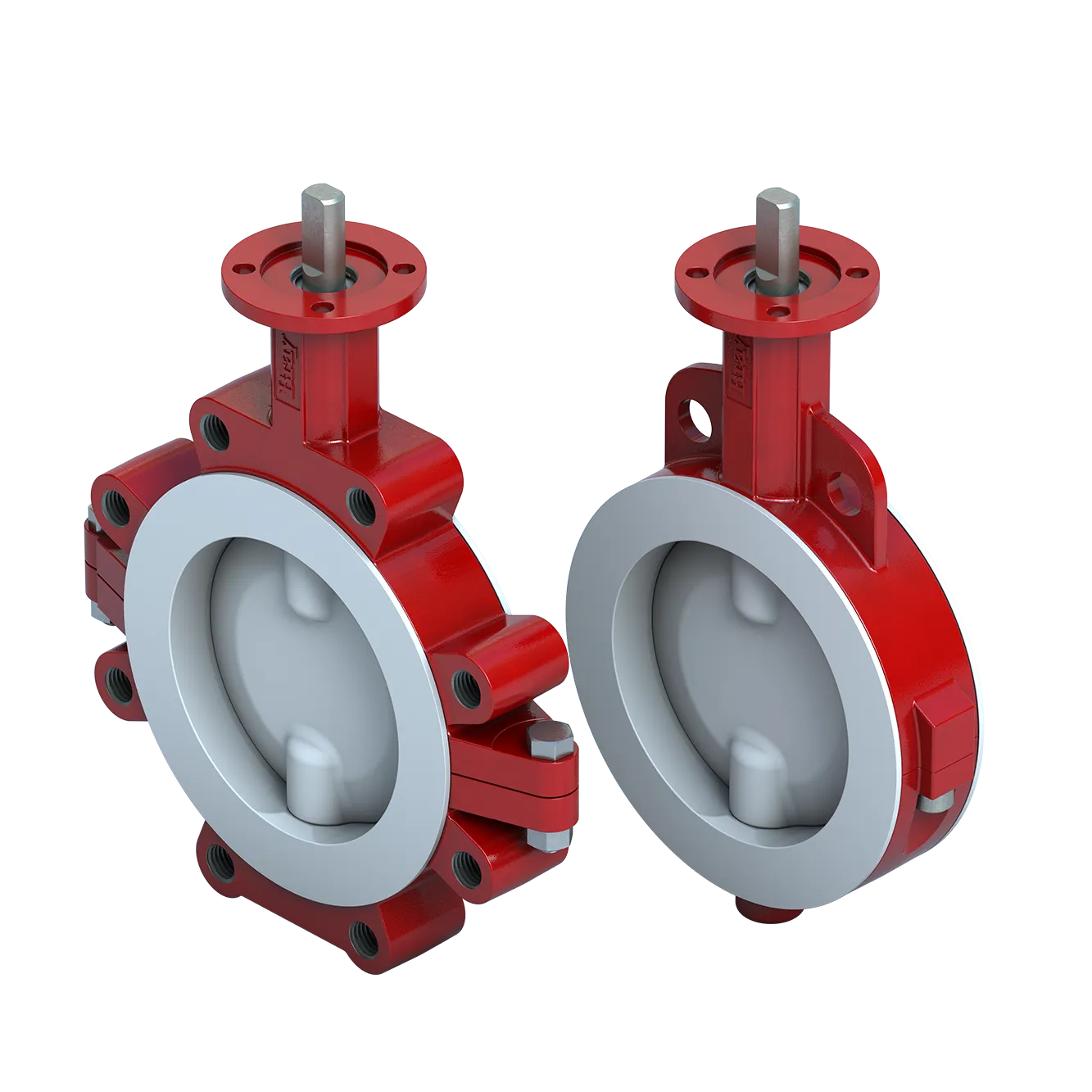
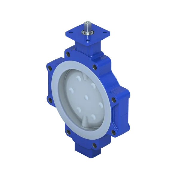
PTFE Lined Butterfly Valve for Corrosion Resistance and Long Service Life
.webp?sfvrsn=92cca52e_1)
More Details
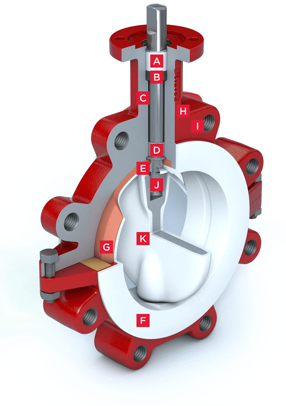
Features & Benefits
-
A. Top Stem Bushing
A top stem bushing, retained by a stainless steel ring, is provided to absorb actuator side thrusts and is acetal as standard or PTFE as an option.
-
B. Upper Stem Seal
The upper stem seal serves to keep any environmental contaminants from entering the stem bore.
-
C. Body
Bodies are two piece wafer or lug style and are polyester coated. All bodies meet full ASME Class 150 pressure ratings for hydrostatic requirements.
-
D. Bearings
PTFE impregnated steel bearings provided for precision alignment of the upper and lower stem.
-
E. Primary Seal
The primary seal is achieved by an interference fit between the extra wide disc hubs and contoured seat.
-
F. Seat Design
The seat design reduces seating/unseating torque and, at the same time, reduces wear on the contacting parts. Curvatures machined into the inner seat area minimize contact forces between the disc and seat as the disc approaches, or opens from, the closed position. This unique seat geometry permits lower torques and reduces seat wear.
-
G. Seat Energizer
A resilient seat energizer extends completely around the seat, including the disc hub. This provides uniform force sufficient for bubble-tight shut off.
-
H. Neck
An extended neck design in all valve sizes allows for 2" (50 mm) of piping insulation and provides easy access for mounting actuators.
-
I. Flange Locating Holes
Locating holes in the wafer version provide quick and precise alignment during valve installation eliminating disc interference with adjacent pipe internal diameter.
-
J. Blowout Proof Stem
A shoulder is machined into the upper stem. The stem and the disc are pressed together during assembly to become one part, thus the design is a positive stem-to-disc drive connection.
-
K. Disc
The lined disc has 1/8" (3 mm) minimum thickness of pure, virgin PTFE or PFA encapsulated over Stainless Steel.


Explore More Bray Insights
Learn Even More About How Bray’s Solutions Can Impact Your Business
ISO-Certified Cleanroom Solutions for Superior Valve Integrity
Cleanroom Valve Services
Bray's state-of-the-art cleanroom facilities deliver ISO Class 6 to ISO Class 9 precision cleaning around the globe where valves are cleaned, inspected, bagged & tagged to meet the most stringent global standards, ensuring contamination-free valves.
Discover Our Precision Cleaning Solutions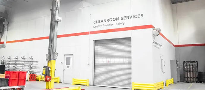
Contact Us
Request A Quote