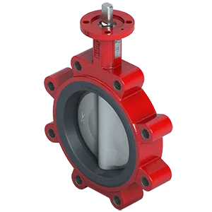
Valve with High Strength Stem Design and Bubble-Tight Shutoff
Reliable Bubble-Tight Shutoff for High-Pressure Environments in Industrial Use

More Details
Features & Benefits

-
A. Modular Design
All Bray manual gear operators, electric and pneumatic actuators mount directly to the S31U, with no brackets required.
-
B. Stem Bushing
Non-corrosive heavy duty acetal bushing absorbs actuator side thrust.
-
C. Stem Seal
Patented stem retaining ring and C-rings prevent unintentional removal of the stem during field service.
-
D. Seat Design
Bray's bonded tongue and groove resilient seat design offers lower torque than many valves on the market today and provides complete isolation of flowing media from all valve components (excluding the disc) by a totally encasing design. The seat features a molded tangential O-ring eliminating any need for flange gaskets.
-
E. Primary & Secondary Seals
These seals prevent line media from coming in contact with the stem or body. Primary Seal is achieved by an interference fit of the molded seat flat with the disc hub. Secondary Seal is created because the stem diameter is greater than the diameter of the seat stem hole.
-
F. Neck
Extended neck length allows for piping insulation and is easily accessible for mounting operators.
-
G. Body
One piece lugged style flange configuration, with a choice of Polyester Coated Ductile Iron/Carbon Steel or uncoated Nickel Aluminum Bronze. All bodies can be drilled to be compatible with ASME 125/150, PN10/16 or other international flange standards.
-
H. Stem
High Strength upper and lower stem incorporate a close tolerance double 'D' disc drive connection. This eliminates stem retention components being exposed to the line media and allows for easy disassembly for maintenance purposes, unlike disc screws and taper pins.
-
I. Disc
Casting is spherically machined and hand polished to provide bubble-tight shutoff with minimum torque and an extended seat life.


Explore More Bray Insights
Learn Even More About How Bray’s Solutions Can Impact Your Business
ISO-Certified Cleanroom Solutions for Superior Valve Integrity
Cleanroom Valve Services
Bray's state-of-the-art cleanroom facilities deliver ISO Class 6 to ISO Class 9 precision cleaning around the globe where valves are cleaned, inspected, bagged & tagged to meet the most stringent global standards, ensuring contamination-free valves.
Discover Our Precision Cleaning Solutions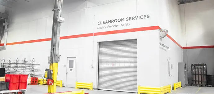
Contact Us
Request A Quote