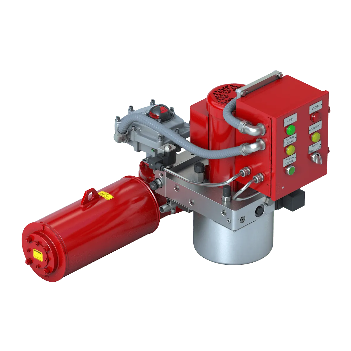
Power Center
Bray designed the Series 70 Hazardous to completely separate the control center from the power center. The power center, located in the actuator base, consists of motor, gear train, capacitor, output drive and heater. This design protects the power drive system as each component has been engineered to require no customer servicing. The power center components have been uniquely configured to maintain the extremely low profile of the Series 70.
Self-Locking Output Drive Assembly
The output drive assembly features a self-locking worm and worm gear drive which holds the valve in the desired position without the need for electro-mechanical braking systems.The worm shaft directly drives the worm gear.
Mechanical Travel Stops
Stainless steel mechanical travel stops are field adjustable to prevent over travel when manual override is in use. The travel stops are located outside the base for easy readjustment without removing the cover. Stainless steel lock nuts with O-ring seals
hold the travel stops securely in place. The travel stops are normally set at the factory to allow 0° and 90° travel.
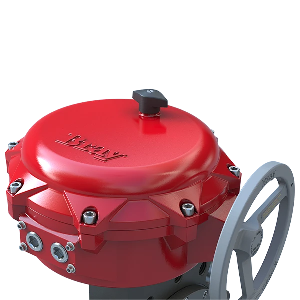
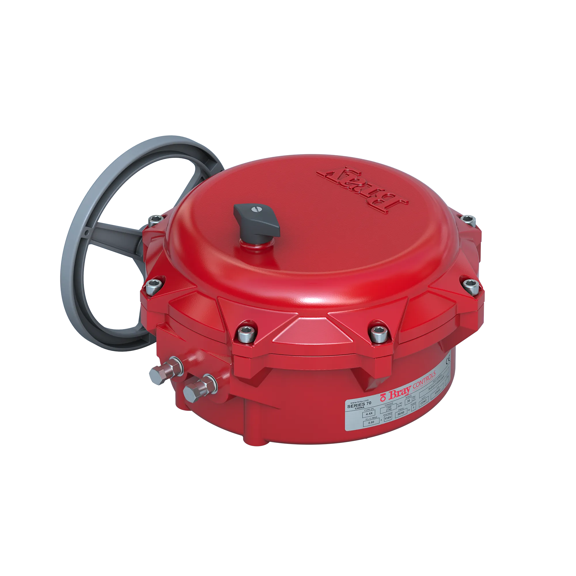
Manual Override Handwheel Assembly
- Pull to engage for manual operation.
- Rotate handwheel to position valve.
- Push to return power operation.
The Bray manual override system ensures positive and fast manual operation without the use of extra tools or levers. When the hand-wheel is engaged, the electrical power to the motor is cut off by means of the automatic power cutout switch. When engaged, the manual override shaft is held in position by a ball detent. The ball detent also holds the shaft in position when the handwheel is pushed in to disengage the override. The drive pin engages and disengages the manual override shaft from the worm and segmented worm gear output shaft. When the handwheel is pushed or pulled, the drive pin smoothly engages the worm shaft.